Gas centrifuge
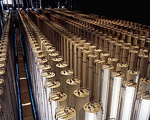
High degrees of separation of these isotopes relies on using many individual centrifuges arranged in series that achieve successively higher concentrations.
American scientist Jesse Beams and his team at the University of Virginia developed the process by separating two chlorine isotopes through a vacuum ultracentrifuge.
It was one of the initial isotopic separation means pursued during the Manhattan Project, more particularly by Harold Urey and Karl P. Cohen, but research was discontinued in 1944 as it was felt that the method would not produce results by the end of the war, and that other means of uranium enrichment (gaseous diffusion and electromagnetic separation) had a better chance of success in the short term.
Franz Simon, Rudolf Peierls, Klaus Fuchs and Nicholas Kurti made important contributions to the centrifugal process.
Paul Dirac made important theoretical contributions to the centrifugal process during World War II;[1][2] Dirac developed the fundamental theory of separation processes that underlies the design and analysis of modern uranium enrichment plants.
[4] Many of the theorists working with Khan were unsure that either gaseous and enriched uranium would be feasible on time.
[5] One scientist recalled: "No one in the world has used the [gas] centrifuge method to produce military-grade uranium....
Enrichment via centrifuge has been used in experimental physics, and the method was smuggled to at least three different countries by the end of the 20th century.
[6] The dense (heavier) molecules move towards the wall, and the lighter ones remain close to the center.
The centrifuge consists of a rigid body rotor rotating at full period at high speed.
A vertical temperature gradient can be applied to create a convective circulation rising in the center and descending at the periphery of the centrifuge.
The gas centrifuge consists of a cylindrical rotor, a casing, an electric motor, and three lines for material to travel.
[4] The cylindrical rotor is located inside the casing, which is evacuated of all air to produce a near frictionless rotation when operating.
[9] Most of the technical details on gas centrifuges are difficult to obtain because they are shrouded in "nuclear secrecy".
[9] The early gas centrifuges used in the UK used an alloy body wrapped in epoxy-impregnated glass fibre.
The early units were typically around 2 metres long, but subsequent developments gradually increased the length.
A section of centrifuges would be fed with variable-frequency alternating current from an electronic (bulk) inverter, which would slowly ramp them up to the required speed, generally in excess of 50,000 rpm.
Thus, in a centrifuge with a baffled top scoop, the wall flow is downwards, and heavier molecules are collected at the bottom.
Thermally induced convection currents can be created by heating the bottom of the centrifuge and/or cooling the top end.
For some uses in nuclear technology, the content of zinc-64 in zinc metal has to be lowered in order to prevent formation of radioisotopes by its neutron activation.