Hemispherical electron energy analyzer
A hemispherical electron energy analyzer or hemispherical deflection analyzer is a type of electron energy spectrometer generally used for applications where high energy resolution is needed—different varieties of electron spectroscopy such as angle-resolved photoemission spectroscopy (ARPES), X-ray photoelectron spectroscopy (XPS) and Auger electron spectroscopy (AES)[1] or in imaging applications such as photoemission electron microscopy (PEEM) and low-energy electron microscopy (LEEM).
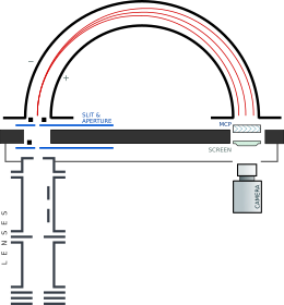
[2] It consists of two concentric conductive hemispheres that serve as electrodes that bend the trajectories of the electrons entering a narrow slit at one end so that their final radii depend on their kinetic energy.
The analyzer, therefore, provides a mapping from kinetic energies to positions on a detector.
In such a system, the electrons are linearly dispersed, depending on their kinetic energy, along the direction connecting the entrance and the exit slit, while the electrons with the same energy are first-order focused.
, are applied to the inner and outer hemispheres, respectively, the electric potential in the region between the two electrodes follows from the Laplace equation: The electric field, pointing radially from the center of the hemispheres out, has the familiar planetary motion
form The voltages are set in such a way that the electrons with kinetic energy
The centripetal force along the path is imposed by the electric field
With this in mind, The potential difference between the two hemispheres needs to be A single pointlike detector at radius
on the other side of the hemispheres will register only the electrons of a single kinetic energy.
The detection can, however, be parallelized because of nearly linear dependence of the final radii on the kinetic energy.
In the past, several discrete electron detectors (channeltrons) were used, but now microchannel plates with phosphorescent screens and camera detection prevail.
for the plane of the great circle for electrons impinging at an angle
with respect to the normal to the entrance, and for the initial radii
to account for the finite aperture and slit widths (typically 0.1 to 5 mm):[4] As can be seen in the pictures of calculated electron trajectories, the finite slit width maps directly into energy detection channels (thus confusing the real energy spread with the beam width).
The angular spread, while also worsening the energy resolution, shows some focusing as the equal negative and positive deviations map to the same final spot.
When these deviations from the central trajectory are expressed in terms of the small parameters
itself is small (of the order of 1°), the final radius of the electron's trajectory,
is acquired, and a single energy channel is smeared over
But there, this additional width is interpreted as energy dispersion, which is, to the first order,
It follows that the instrumental energy resolution, given as a function of the width of the slit,
, of the incoming photoelectrons, which is itself dependent on the width of the aperture and slit, is[2] The analyzer resolution improves with increasing
also improve the resolution, but then the electron transmission probability is reduced, and the signal-to-noise ratio deteriorates accordingly.
The electrostatic lenses in front of the analyzer have two main purposes: they collect and focus the incoming photoelectrons into the entrance slit of the analyzer, and they decelerate the electrons to the range of kinetic energies around
When acquiring spectra in swept (or scanning) mode, the voltages of the two hemispheres – and hence the pass energy – are held fixed; at the same time, the voltages applied to the electrostatic lenses are swept in such a way that each channel counts electrons with the selected kinetic energy for the selected amount of time.
In order to reduce the acquisition time per spectrum, the so-called snapshot (or fixed) mode can be used.
This mode exploits the relation between the kinetic energy of a photoelectron and its position inside the detector.
If the detector energy range is wide enough, and if the photoemission signal collected from all the channels is sufficiently strong, the photoemission spectrum can be obtained in one single shot from the image of the detector.