Incremental encoder
Also, some encoders provide a status output (typically designated alarm)[4] that indicates internal fault conditions such as a bearing failure or sensor malfunction.
Because of this, incremental encoders are commonly used in applications that require precise measurement and control of position and velocity.
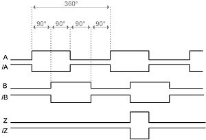
The pulses emitted from the A and B outputs are quadrature-encoded, meaning that when the incremental encoder is moving at a constant velocity, the A and B waveforms are square waves and there is a 90 degree phase difference between A and B.
[2] At any particular time, the phase difference between the A and B signals will be positive or negative depending on the encoder's direction of movement.
When moving at constant velocity, an ideal incremental encoder would output perfect square waves on A and B (i.e., the pulses would be exactly 180° wide and the duty cycle would be 50%) with a phase difference of exactly 90° between A and B signals.
In real encoders, however, due to sensor imperfections and speed variations, the pulse widths are never exactly 180° and the phase difference is never exactly 90°.
Open collector drivers (using an NPN transistor or open drain drivers using an n-type MOSFET) allow operation over a wide range of signal voltages and often can sink significant output current, making them useful for directly driving current loops, opto-isolators and fiber optic transmitters.
Because it cannot source current, the output of an open-collector driver must be connected to a positive DC voltage through a pull-up resistor.
These are well-suited to applications in which the encoder and interface are located near each other (e.g., interconnected via printed circuit conductors or short, shielded cable runs) and powered from a common power supply, thus avoiding exposure to electric fields, ground loops and transmission line effects that might corrupt the signals and thereby disrupt position tracking, or worse, damage the encoder interface.
Examples of this include CMMs and CNC machinery, industrial robotics, factory automation, and motion platforms used in aircraft and spacecraft simulators.
Consequently, the encoder interface must provide RS-422 line receivers to convert the incoming RS-422 pairs to single-ended logic.
Example devices include the balls in mechanical computer mice and trackballs, control knobs in electronic equipment, and rotating shafts in radar antennas.
Some incremental encoder applications lack reference position detectors and therefore must implement homing by other means.
Incremental encoder interfaces are primarily concerned with tracking mechanical displacement and usually do not directly measure speed.
The position signal is inherently quantized, which poses challenges for taking the derivative due to quantization error, especially at low speeds.
In practice, however, it is often necessary to express the speed in standardized units such as meters per second, revolutions per minute (RPM), or miles per hour (MPH).
Upon detecting a state change, it will increment or decrement the position counts based on whether A leads or trails B.
These line receivers serve as buffers to protect downstream interface circuitry and, in many cases, also provide signal conditioning functions.
This type of line receiver inherently rejects low-level noise (by means of its input hysteresis) and protects downstream circuitry from invalid (and possibly destructive) logic signal levels.
This type of receiver rejects common-mode noise and converts the incoming differential signals to the single-ended form required by downstream logic circuits.
Depending on the interface, subsequent processing may include generating an interrupt request upon detecting signal loss, and sending notification to the application for error logging or failure analysis.
An incremental encoder interface largely consists of sequential logic which is paced by a clock signal.
In software-based interfaces, A and B typically are connected to GPIOs that are sampled (via polling or edge interrupts) and debounced by software.
If both the A and B logic states change in consecutive AB samples, the quadrature decoder has no way of determining how many increments, or in what direction the encoder has moved.
Consequently, quadrature decoders often will output an additional error signal which is asserted when the A and B states change simultaneously.
Due to the severity and time-sensitive nature of this condition, the error signal is often connected to an interrupt request.
The clock multiplier of a quadrature decoder is so named because it results in a count rate which is a multiple of the A or B pulse frequency.
The x2 and x1 multipliers allow the counts to change on some, but not all AB state changes, as shown in the quadrature decoder state table above (note: this table shows one of several possible implementations for x2 and x1 multipliers; other implementations may enable counting at different AB transitions).
From an application's perspective, the fundamental purpose of an incremental encoder interface is to report position information on demand.
Depending on the application, this may be as simple as allowing the computer to read the position counter at any time under program control.