I²C
I2C (Inter-Integrated Circuit; pronounced as “eye-squared-see” or “eye-two-see”), alternatively known as I2C or IIC, is a synchronous, multi-controller/multi-target (historically termed as multi-master/multi-slave), single-ended, serial communication bus invented in 1982 by Philips Semiconductors.
It is widely used for attaching lower-speed peripheral integrated circuits (ICs) to processors and microcontrollers in short-distance, intra-board communication.
Several competitors, such as Siemens, NEC, Texas Instruments, STMicroelectronics, Motorola,[1] Nordic Semiconductor and Intersil, have introduced compatible I2C products to the market since the mid-1990s.
I2C bus can be found in a wide range of electronics applications where simplicity and low manufacturing cost are more important than speed.
PC components and systems which involve I2C are serial presence detect (SPD) EEPROMs on dual in-line memory modules (DIMMs), Extended Display Identification Data (EDID) for monitors via VGA, DVI and HDMI connectors, accessing NVRAM chips, etc.
Note that the bit rates are quoted for the transfers between controller (master) and target (slave) without clock stretching or other hardware overhead.
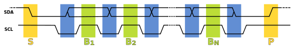
There may be four potential modes of operation for a given bus device, although most devices only use a single role and its two modes: In addition to 0 and 1 data bits, the I2C bus allows special START and STOP signals which act as message delimiters and are distinct from the data bits.
For example, one PMBus operation might reconfigure three power supplies (using three different I2C target addresses), and their new configurations would take effect at the same time: when they receive that STOP.
It is illegal[3]: 14 to transmit a stop marker by releasing SDA to float high again (although such a "void message" is usually harmless), so the next step is to pull SCL low.
The controller then waits for SCL to actually go high; this will be delayed by the finite rise time of the SCL signal (the RC time constant of the pull-up resistor and the parasitic capacitance of the bus) and may be additionally delayed by a target's clock stretching.
Once SCL is high, the controller waits a minimum time (4 μs for standard-speed I2C) to ensure that the receiver has seen the bit, then pulls it low again.
An addressed target device may hold the clock line (SCL) low after receiving (or sending) a byte, indicating that it is not yet ready to process more data.
The controller that is communicating with the target may not finish the transmission of the current bit, but must wait until the clock line actually goes high.
For example, if the target is a microcontroller, its I2C interface could stretch the clock after each byte, until the software decides whether to send a positive acknowledgment or a NACK.
Some controllers, such as those found inside custom ASICs may not support clock stretching; often these devices will be labeled as a "two-wire interface" and not I2C.
Hosts and targets adhering to those limits cannot block access to the bus for more than a short time, which is not a guarantee made by pure I2C systems.
In contrast to protocols (such as Ethernet) that use random back-off delays before issuing a retry, I2C has a deterministic arbitration policy.
[7] The vast majority of applications use I2C in the way it was originally designed—peripheral ICs directly wired to a processor on the same printed circuit board, and therefore over relatively short distances of less than 1 foot (30 cm), without a connector.
Analog switches maintain the bidirectional nature of the lines but do not isolate the capacitance of one segment from another or provide buffering capability.
Alternatively, other types of buffers exist that implement current amplifiers or keep track of the state (i.e. which side drove the bus low) to prevent latch-up.
(SDA is set/sampled after SCL to avoid false state detection) (Byte received from sender) (Byte not received from sender) Rest of the read or write message goes here Rest of the read or write message goes here Two groups of 8 addresses each are reserved for special functions: In addition, the remaining 112 addresses are designated for specific classes of device, and some of them are further reserved by either related standards or common usage.
The device ID protocol requires a single transaction; targets are forbidden from responding if they observe a stop symbol.
Configuration, calibration or self-test modes which cause the target to respond unusually are also often automatically terminated at the end of a transaction.
Software for attached devices is written to call a "bus driver" that handles the actual low-level I2C hardware.
This permits the driver code for attached devices to port easily to other hardware, including a bit-banging design.
Logic analyzers display time stamps of each signal level change, which can help find protocol problems.
I2C nodes implemented in software (instead of dedicated hardware) may not even support the 100 kbit/s speed; so the whole range defined in the specification is rarely usable.
Bus capacitance also places a limit on the transfer speed, especially when current sources are not used to decrease signal rise times.
For example, if any device holds the SDA or SCL line low, it prevents the controller from sending START or STOP commands to reset the bus.
Another might be used to control a few devices where latency and throughput are not important issues; yet another segment might be used only to read EEPROM chips describing add-on cards (such as the SPD standard used with DRAM sticks).