Image filter end terminations
Filters designed using the image impedance methodology suffer from a peculiar flaw in the theory.
This article explains how the effects of image filter end terminations can be taken into account.
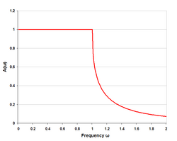
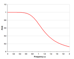
Generally, the effect of the terminations is to cause a rounding of the frequency response at cut-off.
Another prediction of the image method is zero loss in the passband (assuming ideal lossless components).
The transfer function of any filter connected as shown in the diagram above is given by the expression where Note that Vi is the nominal voltage that would be delivered by the generator if it were terminated in its characteristic impedance (i.e. R1), not the actual voltage appearing at the input terminals of the filter.
The magnitude of the transfer function is given by where for the passband, and for the stopband, A similar simplification can be made for lossless antimetrical filters.
Antimetrical, in this context, means that the filter image impedances and terminations at each end are the dual of each other.
In the vast majority of cases the filter design will be either symmetrical or antimetrical and one of these reduced expressions will apply.