Zobel network
Zobel networks are a type of filter section based on the image-impedance design principle.
They are named after Otto Zobel of Bell Labs, who published a much-referenced paper on image filters in 1923.
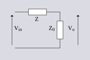
[1] The distinguishing feature of Zobel networks is that the input impedance is fixed in the design independently of the transfer function.
This characteristic is achieved at the expense of a much higher component count compared to other types of filter sections.
If Zobel networks are used however, it is only necessary to measure the line response into a fixed resistive load and then design an equaliser to compensate it.
This is a tremendous advantage where high quality lines with flat frequency responses are desired.
The most significant effect that needs to be compensated for is that at some cut-off frequency the line response starts to roll-off like a simple low-pass filter.
The effective bandwidth of the line can be increased with a section that is a high-pass filter matching this roll-off, combined with an attenuator.
Quite commonly in telecomms networks, a circuit is made up of two sections of line which do not have the same characteristic impedance.
Occasionally, a low-pass section is included to compensate for excessive line transformer roll-off at the low frequency end.
This in turn has the effect of slightly reducing the amount of LF lift the section would otherwise have produced.
The basic loss of the section can be increased by the same amount as the stray resistance is inserting and this will return the LF lift achieved to that designed for.
This is followed by a fixed gain amplifier to bring the signal back up to a usable level, typically 0 dBu.
Any more and the amplification of line noise will tend to cancel out the quality benefits of improved bandwidth.
A good quality transformer (usually essential, but not shown on the diagram), known as a repeating coil, is at the beginning of the chain where the line terminates.
The Zobel networks described here can be used to equalise land lines composed of twisted pair or star quad cables.
The balanced circuit nature of these lines delivers a good common mode rejection ratio (CMRR).
Its topology makes it intrinsically balanced but it is never used to implement the constant resistance filters of the kind described here because of the increased component count.
There is however, one common application for this topology, the lattice phase equaliser, which is also constant resistance and also invented by Zobel.
A half section is either the series impedance (series half-section) or shunt admittance (shunt half-section) that, when connected between source and load impedances of R0, will result in the same transfer function as some arbitrary constant resistance circuit.
The purpose of using half sections is that the same functionality is achieved with a drastically reduced component count.
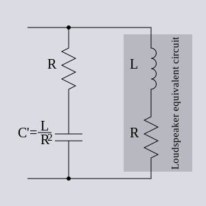
Zobel networks can be used to make the impedance a loudspeaker presents to its amplifier output appear as a steady resistance.
The resistance represents the energy transferred from the amplifier to the sound output plus some heating losses in the loudspeaker.
A parallel circuit of a series resistor and capacitor of the correct values will form a Zobel bridge.
From this design approach there is no difference in the order of the capacitor and the resistor and Boucherot cell might be considered a more accurate description.
Since the impedance of the Bode network can be either capacitive or inductive depending on the position of the adjustment potentiometer, the response may be a boost or a cut to the band of frequencies it is acting on.
Optionally, there may be an inductor included in series with the first capacitor which increases the equalisation at the high end due to the steeper slope produced as resonance is approached.
With the Zobel Bode equaliser, this is a simple matter of ganging two pots together - a component configuration available off-the-shelf.
These equalisers tend to be "hand built", one solution being to select the capacitors on test and fit fixed values according to the measurements and then adjust the inductors until the required match is achieved.
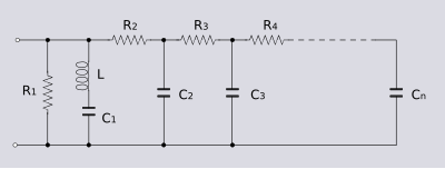
The furthest element of the ladder from the driving point is equalising the lowest frequency of interest.