Kinematics
Then, using arguments from geometry, the position, velocity and acceleration of any unknown parts of the system can be determined.
The term kinematic is the English version of A.M. Ampère's cinématique,[9] which he constructed from the Greek κίνημα kinema ("movement, motion"), itself derived from κινεῖν kinein ("to move").
[10][11] Kinematic and cinématique are related to the French word cinéma, but neither are directly derived from it.
For example, consider a tower 50 m south from your home, where the coordinate frame is centered at your home, such that east is in the direction of the x-axis and north is in the direction of the y-axis, then the coordinate vector to the base of the tower is r = (0 m, −50 m, 0 m).
In the most general case, a three-dimensional coordinate system is used to define the position of a particle.
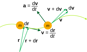
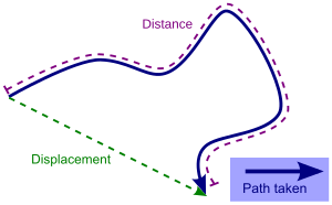
Consider the ratio formed by dividing the difference of two positions of a particle (displacement) by the time interval.
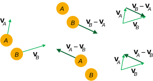
Alternatively, this same result could be obtained by computing the time derivative of the relative position vector rB/A.
Alternatively, this same result could be obtained by computing the second time derivative of the relative position vector rB/A.
This reduces the parametric equations of motion of the particle to a Cartesian relationship of speed versus position.
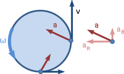
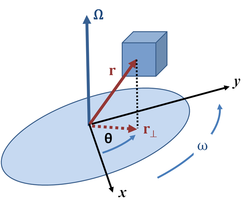
If the trajectory of the particle is constrained to lie on a cylinder, then the radius r is constant and the velocity and acceleration vectors simplify.
A special case of a particle trajectory on a circular cylinder occurs when there is no movement along the z axis:
If the structural stiffness of the parts are sufficient, then their deformation can be neglected and rigid transformations can be used to define this relative movement.
[19] These transformations can cause the displacement of the triangle in the plane, while leaving the vertex angle and the distances between vertices unchanged.
The set of rigid transformations in an n-dimensional space is called the special Euclidean group on Rn, and denoted SE(n).
The combination of a rotation and translation in the plane R2 can be represented by a certain type of 3×3 matrix known as a homogeneous transform.
The 3×3 homogeneous transform is constructed from a 2×2 rotation matrix A(φ) and the 2×1 translation vector d = (dx, dy), as:
In particular, let r define the coordinates of points in a reference frame M coincident with a fixed frame F. Then, when the origin of M is displaced by the translation vector d relative to the origin of F and rotated by the angle φ relative to the x-axis of F, the new coordinates in F of points in M are given by:
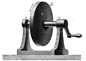
Objects like a playground merry-go-round, ventilation fans, or hinged doors can be modeled as rigid bodies rotating about a single fixed axis.
This allows the description of a rotation as the angular position of a planar reference frame M relative to a fixed F about this shared z-axis.
is known as the angular velocity matrix of M relative to F. The parameter ω is the time derivative of the angle θ, that is:
Important formulas in kinematics define the velocity and acceleration of points in a moving body as they trace trajectories in three-dimensional space.
The acceleration of a point P in a moving body B is obtained as the time derivative of its velocity vector:
An object that rolls against a surface without slipping obeys the condition that the velocity of its center of mass is equal to the cross product of its angular velocity with a vector from the point of contact to the center of mass:
This is the case where bodies are connected by an idealized cord that remains in tension and cannot change length.
Another example is a drum turned by the pull of gravity upon a falling weight attached to the rim by the inextensible cord.
[26] Reuleaux called the ideal connections between components that form a machine kinematic pairs.
[27] A lower pair is an ideal joint, or holonomic constraint, that maintains contact between a point, line or plane in a moving solid (three-dimensional) body to a corresponding point line or plane in the fixed solid body.
Similarly, the contact between the involute curves that form the meshing teeth of two gears are cam joints.
This formula can also be used to enumerate the topologies of kinematic chains that have a given degree of freedom, which is known as type synthesis in machine design.
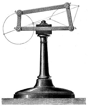
The planar one degree-of-freedom linkages assembled from N links and j hinges or sliding joints are: For larger chains and their linkage topologies, see R. P. Sunkari and L. C. Schmidt, "Structural synthesis of planar kinematic chains by adapting a Mckay-type algorithm", Mechanism and Machine Theory #41, pp.