Jerk (physics)
Jerk is most commonly denoted by the symbol j and expressed in m/s3 (SI units) or standard gravities per second (g0/s).
In balancing a given force, such as holding up a weight, the postcentral gyrus establishes a control loop to achieve the desired equilibrium.
If the force changes too quickly, the muscles cannot relax or tense fast enough and overshoot in either direction, causing a temporary loss of control.
To avoid vehicle passengers losing control over body motion and getting injured, it is necessary to limit the exposure to both the maximum force (acceleration) and maximum jerk, since time is needed to adjust muscle tension and adapt to even limited stress changes.
[2] Excessive jerk may also result in an uncomfortable ride, even at levels that do not cause injury.
Engineers expend considerable design effort minimizing "jerky motion" on elevators, trams, and other conveyances.
In classical mechanics of rigid bodies, there are no forces associated with the derivatives of acceleration; however, physical systems experience oscillations and deformations as a result of jerk.
In designing the Hubble Space Telescope, NASA set limits on both jerk and jounce.
Discontinuities in acceleration do not occur in real-world environments because of deformation, quantum mechanics effects, and other causes.
Extrapolating from these idealized settings, one can qualitatively describe, explain and predict the effects of jerk in real situations.
Jump-discontinuity in acceleration can be modeled using a Dirac delta function in jerk, scaled to the height of the jump.
Now assume a point particle moves with constant speed along this path, so its tangential acceleration is zero.
The frictional force, torque, and car deceleration suddenly reach zero, which indicates a Dirac delta in physical jerk.
The Dirac delta is smoothed down by the real environment, the cumulative effects of which are analogous to damping of the physiologically perceived jerk.
This example neglects the effects of tire sliding, suspension dipping, real deflection of all ideally rigid mechanisms, etc.
Consider a rigid body rotating about a fixed axis in an inertial reference frame.
Because of the finite thickness of the driving wheel's fork (the slot for the driving pin), this device generates a discontinuity in the angular acceleration α, and an unbounded angular jerk ζ in the driven wheel.
Generally, combined contacts may be used to avoid the jerk (and wear and noise) associated with a single follower (such as a single follower gliding along a slot and changing its contact point from one side of the slot to the other can be avoided by using two followers sliding along the same slot, one side each).An elastically deformable mass deforms under an applied force (or acceleration); the deformation is a function of its stiffness and the magnitude of the force.
Also shown, for angular jerk, are the deformation waves propagating in a circular pattern, which causes shear stress and possibly other modes of vibration.
The reflection of waves along the boundaries cause constructive interference patterns (not pictured), producing stresses that may exceed the material's limits.
The deformation waves may cause vibrations, which can lead to noise, wear, and failure, especially in cases of resonance.
To reduce the amplitude of excited stress waves and vibrations, one can limit jerk by shaping motion and making the acceleration continuous with slopes as flat as possible.
Due to limitations of abstract models, algorithms for reducing vibrations include higher derivatives, such as jounce, or suggest continuous regimes for both acceleration and jerk.
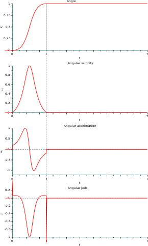
An Euler spiral, the theoretically optimum transition curve, linearly increases centripetal acceleration and results in constant jerk (see graphic).
The incline causes vertical acceleration, which is a design consideration for wear on the track and embankment.
[7] ISO 8100-34[8] specifies measurement methods for elevator ride quality with respect to jerk, acceleration, vibration, and noise; however, the standard does not specify levels for acceptable or unacceptable ride quality.
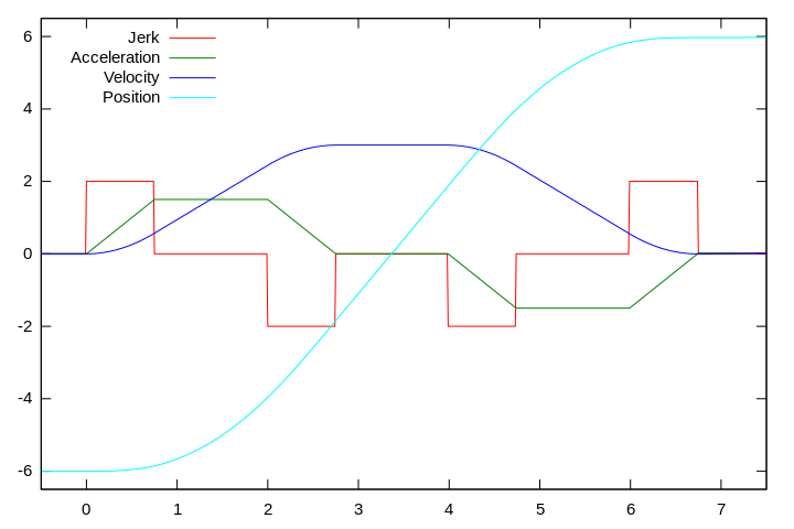
A primary design goal for motion control is to minimize the transition time without exceeding speed, acceleration, or jerk limits.
Consider a third-order motion-control profile with quadratic ramping and deramping phases in velocity (see figure).
If this modification does not sufficiently reduce the crossed distance, then segments one, three, five, and seven could be shortened by an equal amount, and the constant acceleration limits would not be reached.
Motion profiles are tailored for specific applications including machines, people movers, chain hoists, automobiles, and robotics.