Log amplifier
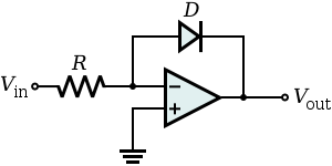
Log amplifier circuits designed with operational amplifiers (opamps) use the exponential current–voltage relationship of a p–n junction (either from a diode or bipolar junction transistor) as negative feedback to compute the logarithm.
Temperature-compensated log amplifiers may include more than one opamp and use closely-matched circuit elements to cancel out temperature dependencies.
Additionally, signals that were companded by a log amplifier may later be expanded by an exponentiator to return to their original scale.
the diode's current is approximately proportional to an exponential function: Rearranging this equation gives the output voltage
to be approximately: An input voltage can easily be scaled and converted into the diode's current
doubles for every ten kelvin rise in temperature and varies significantly due to process variation.
of a real diode limits accuracy at high currents due to an added
And, diffusion currents in surface inversion layers and generation-recombination effects in space-charge regions cause a scale factor
But this non-logarithmic behavior itself is often lost in this device noise, which limits the dynamic range to 40-60 dB, but the dynamic range can be increased to over 120 dB by replacing the diode with a transistor in a "transdiode" configuration.
or smaller and the question of how to handle negative inputs, one solution uses a symmetric function such as the inverse hyperbolic sine, whose graph approximates
[5] While the floating diode in the earlier basic opamp implementation causes the output voltage to depend on the opamp's input offset current, the grounded-base or "transdiode" configuration shown in the diagram does not possess this problem.
Negative feedback causes the opamp to output enough voltage on the base-emitter junction of the bipolar junction transistor (BJT) to ensure that all available input current is drawn through the collector of the BJT, so the output voltage is then referenced relative to the true ground of the transistor's base rather than the virtual ground.
negative enough to forward bias the emitter-base junction of the BJT (to keep it in the active mode of operation), then: where
Because temperature compensation is generally needed, it is often built into log amplifier ICs.
Some analog computation chips that follow log operations by an antilog may conveniently compensate the log circuit's temperature variation by a similar variation in the antilog circuit.
temperature dependence is to copy the basic uncompensated BJT-based log amplifier, but use a constant current source instead of resistor
The BJTs should be matched and in thermal equilibrium, so that the difference amplifier subtracts the second BJT's junction voltage to cancel out
Using a resistive temperature detector (e.g. a thermistor[1]) in the difference amplifier's gain-setting resistors can minimize the remaining
[6] Such architectures can be very accurate; for instance, the LOG200 chip released in 2024 achieves 160 dB dynamic range with under 0.2% log conformity error.
[7] Texas Instruments application note AN-311 describes another temperature-compensated circuit which only uses two opamps instead of three and maintains 1% log conformity.
The second BJT's collector is fed a constant current from a temperature-compensated Zener diode voltage reference and its emitter is tied to the emitter of the first BJT, which also connects through a resistor the output of the second opamp.
is outputted through the midpoint of a temperature-compensated voltage divider (where one resistor has a much higher temperature coefficient) to counteract
[8] While the previous circuits utilized the p–n junction's exponential current–voltage relationship for computing the log function, the following approaches instead approximate the log function by cascading multiple simpler amplifiers.
A basic multistage log amp works by cascading a series of N linear amplifiers, each with gain of A dB, and then summing the result.
For small signals such that the final amplifier doesn't saturate, the total gain will be N·A dB.
However, as the input signal level increases, the final amplifier will limit and thus make a fixed contribution to the sum, so that the gain will drop to (N-1)·A dB.
[9] If limiting amplifiers that clip "softly" are cascaded without summing, the approximation (which can be within 0.1 dB) is sometimes called a "true log amp".
The response of both this true log amp and the basic multistage log amp are not truly logarithmic, because they are symmetric about zero (while the mathematical logarithm function is indeterminate for negative inputs) and are linear for small inputs.
But, such a symmetrical transfer function is fine for capacitively coupled AC inputs, such as from radar receivers.
[1] The successive detection log amp architecture is a variant of this which uses full or half wave detectors from the output of each amplifier stage, all connected to the log amplifier's output node.