Loop antenna
Large loop antennas can be thought of as folded dipoles whose parallel wires have been split apart and opened out into some oval or polygonal shape.
[2] A rectangle twice as high as its width obtains slightly increased gain and also matches 50 Ω directly if used as a single element.
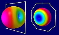
As the frequency progresses to the second and third resonances, the perpendicular radiation fades and strong lobes near the plane of the loop arise.
[3](p 235) At the lower shortwave frequencies, a full loop is physically quite large, and its only practical installation is "lying flat", with the plane of the loop horizontal to the ground and the antenna wire supported at the same relatively low height by masts along its perimeter.
[2] This results in horizontally-polarized radiation, which peaks toward the vertical near the lowest harmonic; that pattern is good for regional NVIS communication, but unfortunately is not generally useful for making continental-scale contacts.
[f] Because of its much greater radiation resistance, a halo presents a good impedance match to 50-Ohm coaxial cable, and its construction is less demanding than a small loop, since the maker is not compelled to take such extreme care to avoid losses from mediocre conductors and contact resistance.
On the VHF bands and above, the physical diameter of a halo is small enough to be effectively used as a mobile antenna.
Halos pick up less nearby electrical spark interference than monopoles and dipoles, such as ignition noise from vehicles.
[5] Although it has a superficially different appearance, the halo antenna can conveniently be analyzed as a dipole (which also has a half-wave radiating part with a high voltage and zero current at its ends) that has been bent into a circle.
The gap in the halo is electrically equivalent to the tuning capacitor on a small loop, although the incidental capacitance involved is not nearly as large.
They are thus mainly used as receiving antennas at lower frequencies (wavelengths of tens to hundreds of meters).
Several performance factors, including received power, scale in proportion to the loop's area.
Small receiving loops are typically used below 14 MHz, where human-made and natural atmospheric noise dominate.
Thus the signal-to-noise ratio of the received signal will not be adversely affected by low efficiency as long as the loop is not excessively small.
[h] Consequently, most of the power delivered to a small loop antenna will be converted to heat by the loss resistance, rather than doing useful work pushing out radio waves or gathering them in.
So the quieter the rising frequency gets, the more convenient it is to replace a small receiving loop with a larger, but still relatively compact, halos.
In order to couple to a transmitter or receiver, the inductive reactance is normally canceled with a parallel capacitance.
[k] Since a good loop antenna will have a high Q factor (narrow bandwidth), the capacitor must be variable and is adjusted to match the receiver's tuning.
Small-loop receiving antennas are also almost always resonated using a parallel-plate capacitor, which makes their reception narrow-band, sensitive only to a very specific frequency.
Often, at mediumwave and lower shortwave frequencies, Litz wire is used for the winding to reduce skin effect losses.
Elaborate "basket weave" patterns are used at all frequencies to reduce inter-winding capacitance in the coil insuring that the loop self-resonance is well above the operating frequency, so that it acts as an electrical inductor that can be resonated with a tuning capacitor, and with a consequent improvement of the loop Q factor.
Inclusion of a magnetically permeable core increases the radiation resistance of a small loop,[1] mitigating the inefficiency due to ohmic losses.
Vertically aligned small loops are used in military land-mobile radio, at frequencies of 3–7 MHz, because of their ability to direct energy upwards, unlike a conventional whip antenna.
This enables near vertical incidence skywave (NVIS) communication up to 300 km (190 miles) in mountainous regions.
One practical issue with small loops as transmitting antennas is that a small transmitting loop has not only a very large current going through it, but also a very high voltage across the capacitor – typically thousands of volts – even when fed with only a few watts of transmitter power.
But because reducing loss resistance increases the antenna's Q, the consequence of better efficiency is even greater voltage across the capacitor at the loop's gap.
[l] The high antenna voltage is generally troublesome only on the upper end of a whip's loading coil, since it is spread across the extended coil length, whereas high voltages on a loop's capacitor plates are (ideally) at maximum over all of the plate surfaces.
Further, the high-voltage tips of monopoles and dipoles typically are mounted high up and far out of reach, which limits opportunities for radio-frequency burns.
Although the magnetic coils in these inductive systems sometimes seem indistinguishable from the small loop antennas discussed above, such devices can only operate over short distances, and are specifically designed to avoid transmitting or receiving radio waves.
Because inductive heating systems and RFID readers only use near-field alternating magnetic fields, their performance criteria are dissimilar to the far-field radio antennas discussed in this article.