Impedance matching
For example, impedance matching typically is used to improve power transfer from a radio transmitter via the interconnecting transmission line to the antenna.
Techniques of impedance matching include transformers, adjustable networks of lumped resistance, capacitance and inductance, or properly proportioned transmission lines.
In simple cases (such as low-frequency or direct current power transmission) the reactance may be negligible or zero; the impedance can be considered a pure resistance, expressed as a real number.
Another reason was to ensure correct operation of the hybrid transformers used at central exchange equipment to separate outgoing from incoming speech, so these could be amplified or fed to a four-wire circuit.
Most modern audio circuits, on the other hand, use active amplification and filtering and can use voltage-bridging connections for greatest accuracy.
To match electrical impedances, engineers use combinations of transformers, resistors, inductors, capacitors and transmission lines.
These passive (and active) impedance-matching devices are optimized for different applications and include baluns, antenna tuners (sometimes called ATUs or roller-coasters, because of their appearance), acoustic horns, matching networks, and terminators.
The formula for calculating the transformer turns ratio for this example is: Resistive impedance matches are easiest to design and can be achieved with a simple L pad consisting of two resistors.
Power loss is an unavoidable consequence of using resistive networks, and they are only (usually) used to transfer line level signals.
By controlling the position of each element, a broad range of load impedances can be matched without having to reconnect the circuit.
Filters are frequently used to achieve impedance matching in telecommunications and radio engineering.
In general, it is not theoretically possible to achieve perfect impedance matching at all frequencies with a network of discrete components.
Applications requiring only a narrow bandwidth, such as radio tuners and transmitters, might use a simple tuned filter such as a stub.
If a reactance is in parallel with the source, the effective network matches from high to low impedance.
Multiple L-sections can be wired in cascade to achieve higher impedance ratios or greater bandwidth.
Transmission line matching networks can be modeled as infinitely many L-sections wired in cascade.
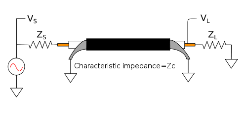
In RF connections, impedance matching is desirable, because otherwise reflections may be created at the end of the mismatched transmission line.
In radio-frequency (RF) systems, a common value for source and load impedances is 50 ohms.
is the one-way transfer function (from either end to the other) when the transmission line is exactly matched at source and load.
As the signals are sent and received on the same two-wire circuit to the central office (or exchange), cancellation is necessary at the telephone earpiece so excessive sidetone is not heard.
All devices used in telephone signal paths are generally dependent on matched cable, source and load impedances.
Each country has its own standard for these networks, but they are all designed to approximate about 600 ohms over the voice frequency band.
If they are properly balanced, there is no need for a transformer or a large electrolytic capacitor to separate AC from DC current.
Similar to electrical transmission lines, an impedance matching problem exists when transferring sound energy from one medium to another.
If the acoustic impedance of the two media are very different most sound energy will be reflected (or absorbed), rather than transferred across the border.
The gel used in medical ultrasonography helps transfer acoustic energy from the transducer to the body and back again.
Without the gel, the impedance mismatch in the transducer-to-air and the air-to-body discontinuity reflects almost all the energy, leaving very little to go into the body.
Acoustic impedance matching (or the lack of it) affects the operation of a megaphone, an echo and soundproofing.
A similar effect occurs when light (or any electromagnetic wave) hits the interface between two media with different refractive indices.
In this case, the masses act as "mechanical impedances",[dubious – discuss] which must be matched to maximize energy transfer.