Phased array
In a simple array antenna, the radio frequency current from the transmitter is fed to multiple individual antenna elements with the proper phase relationship so that the radio waves from the separate elements combine (superpose) to form beams, to increase power radiated in desired directions and suppress radiation in undesired directions.
Since the size of an antenna array must extend many wavelengths to achieve the high gain needed for narrow beam-width, phased arrays are mainly practical at the high frequency end of the radio spectrum, in the UHF and microwave bands, in which the operating wavelengths are conveniently small.
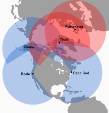
Phased arrays were originally conceived for use in military radar systems, to steer a beam of radio waves quickly across the sky to detect planes and missiles.
Active arrays are a more advanced, second-generation phased-array technology that are used in military applications; unlike PESAs they can radiate several beams of radio waves at multiple frequencies in different directions simultaneously.
The AN/SPS-33 -- installed on the nuclear-powered ships Long Beach and Enterprise around 1961 -- was claimed to be the only operational 3-D phased array in the world in 1966.
[18] In 2004, Caltech researchers demonstrated the first integrated silicon-based phased array receiver at 24 GHz with 8 elements.
In 2007, DARPA researchers announced a 16-element phased-array radar antenna which was also integrated with all the necessary circuits on a single silicon chip and operated at 30–50 GHz.
Simultaneous electrical scanning in both azimuth and elevation was first demonstrated in a phased array antenna at Hughes Aircraft Company, California in 1957.
Phased arrays are used by many AM broadcast radio stations to enhance signal strength and therefore coverage in the city of license, while minimizing interference to other areas.
Due to the differences between daytime and nighttime ionospheric propagation at mediumwave frequencies, it is common for AM broadcast stations to change between day (groundwave) and night (skywave) radiation patterns by switching the phase and power levels supplied to the individual antenna elements (mast radiators) daily at sunrise and sunset.
For example, because of the rapidity with which the beam can be steered, phased array radars allow a warship to use one radar system for surface detection and tracking (finding ships), air detection and tracking (finding aircraft and missiles) and missile uplink capabilities.
Before using these systems, each surface-to-air missile in flight required a dedicated fire-control radar, which meant that radar-guided weapons could only engage a small number of simultaneous targets.
During the terminal portion of the flight, continuous-wave fire control directors provide the final guidance to the target.
The AN/SPY-1 phased array radar, part of the Aegis Combat System deployed on modern U.S. cruisers and destroyers, "is able to perform search, track and missile guidance functions simultaneously with a capability of over 100 targets.
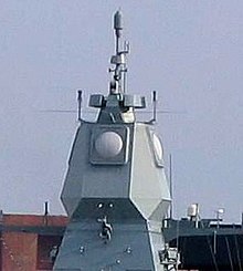
"[25] Likewise, the Thales Herakles phased array multi-function radar used in service with France and Singapore has a track capacity of 200 targets and is able to achieve automatic target detection, confirmation and track initiation in a single scan, while simultaneously providing mid-course guidance updates to the MBDA Aster missiles launched from the ship.
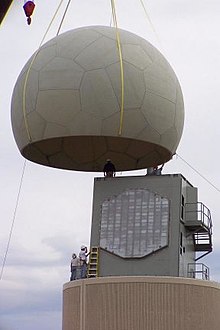
[28] The National Severe Storms Laboratory has been using a SPY-1A phased array antenna, provided by the US Navy, for weather research at its Norman, Oklahoma facility since April 23, 2003.
Current project participants include the National Severe Storms Laboratory and National Weather Service Radar Operations Center, Lockheed Martin, United States Navy, University of Oklahoma School of Meteorology, School of Electrical and Computer Engineering, and Atmospheric Radar Research Center, Oklahoma State Regents for Higher Education, the Federal Aviation Administration, and Basic Commerce and Industries.
The project includes research and development, future technology transfer and potential deployment of the system throughout the United States.
[29] A team from Japan's RIKEN Advanced Institute for Computational Science (AICS) has begun experimental work on using phased-array radar with a new algorithm for instant weather forecasts.
The dynamic beam forming in an optical phased array transmitter can be used to electronically raster or vector scan images without using lenses or mechanically moving parts in a lensless projector.
[32] Optical phased array receivers have been demonstrated to be able to act as lensless cameras by selectively looking at different directions.
It is designed to provide broadband internet connectivity to consumers; the user terminals of the system will use phased array antennas.
A graduated attenuation window is sometimes applied across the face of the array to improve side-lobe suppression performance, in addition to the phase shift.
As an example, an antenna with a 2-degree beam with a pulse rate of 1 kHz will require approximately 8 seconds to cover an entire hemisphere consisting of 8,000 pointing positions.
This configuration provides 12 opportunities to detect a 1,000 m/s (2,200 mph; 3,600 km/h) vehicle over a range of 100 km (62 mi), which is suitable for military applications.
[citation needed] The position of mechanically steered antennas can be predicted, which can be used to create electronic countermeasures that interfere with radar operation.
The flexibility resulting from phased array operation allows beams to be aimed at random locations, which eliminates this vulnerability.
The SPS-48 radar uses multiple transmit frequencies with a serpentine delay line along the left side of the array to produce vertical fan of stacked beams.
Passive phased arrays typically use large amplifiers that produce all of the microwave transmit signal for the antenna.
Phase shifters typically consist of waveguide elements controlled by magnetic field, voltage gradient, or equivalent technology.