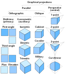
Multiview orthographic projection
In technical drawing and computer graphics, a multiview projection is a technique of illustration by which a standardized series of orthographic two-dimensional pictures are constructed to represent the form of a three-dimensional object.
In each, the appearances of views may be thought of as being projected onto planes that form a six-sided box around the object.
Although six different sides can be drawn, usually three views of a drawing give enough information to make a three-dimensional object.
To render each such picture, a ray of sight (also called a projection line, projection ray or line of sight) towards the object is chosen, which determines on the object various points of interest (for instance, the points that are visible when looking at the object along the ray of sight); those points of interest are mapped by an orthographic projection to points on some geometric plane (called a projection plane or image plane) that is perpendicular to the ray of sight, thereby creating a 2D representation of the 3D object.
An elevation is a common method of depicting the external configuration and detailing of a 3-dimensional object in two dimensions.
The elevations specify the composition of the different facades of the building, including ridge heights, the positioning of the final fall of the land, exterior finishes, roof pitches, and other architectural details.
For example, the north and west views may be shown side-by-side, sharing an edge, even though this does not represent a proper orthographic projection.
Modern orthographic projection is derived from Gaspard Monge's descriptive geometry.
[4] Monge defined a reference system of two viewing planes, horizontal H ("ground") and vertical V ("backdrop").
The 3D object of interest is then placed into either quadrant I or III (equivalently, the position of the intersection line between the two planes is shifted), obtaining first- and third-angle projections, respectively.
The terminology of quadrant is a mild anachronism, as a modern orthographic projection with three views corresponds more precisely to an octant of 3D space.
A two-dimensional representation of the object is then created by "unfolding" the box, to view all of the interior walls.
BS 308 (Part 1) Engineering Drawing Practice, gave the option of using both projections, but generally, every illustration (other than the ones explaining the difference between first and third-angle) was done in first-angle.
A great deal of confusion has ensued in drafting rooms and engineering departments when drawings are transferred from one convention to another.
Orthographic multiview projection is derived from the principles of descriptive geometry and may produce an image of a specified, imaginary object as viewed from any direction of space.
Above, a technique is described that obtains varying views by projecting images after the object is rotated to the desired position.
To obtain this view without multiple rotations requires the principles of Descriptive Geometry.
[5] Third-angle projection is most commonly used in America,[6] Japan (in JIS B 0001:2010);[7] and is preferred in Australia, as laid down in AS 1100.101—1992 6.3.3.
BS 308 (Part 1) Engineering Drawing Practice BS 8888 Technical product documentation and specification ISO 5456-2 Technical drawings – Projection methods – Part 2: Orthographic Representations (includes the truncated cone symbol)