Steam turbine
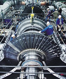
[1][2] Fabrication of a modern steam turbine involves advanced metalwork to form high-grade steel alloys into precision parts using technologies that first became available in the 20th century; continued advances in durability and efficiency of steam turbines remains central to the energy economics of the 21st century.
[3] Technical challenges include rotor imbalance, vibration, bearing wear, and uneven expansion (various forms of thermal shock).
[11] The modern steam turbine was invented in 1884 by Charles Parsons, whose first model was connected to a dynamo that generated 7.5 kilowatts (10.1 hp) of electricity.
[12] The invention of Parsons' steam turbine made cheap and plentiful electricity possible and revolutionized marine transport and naval warfare.
He taught at the École des mines de Saint-Étienne for a decade until 1897, and later founded a successful company that was incorporated into the Alstom firm after his death.
One of the founders of the modern theory of steam and gas turbines was Aurel Stodola, a Slovak physicist and engineer and professor at the Swiss Polytechnical Institute (now ETH) in Zurich.
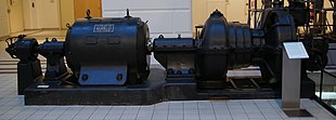
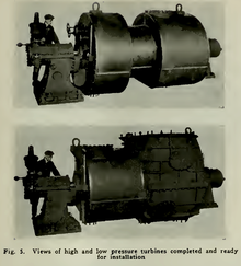
The steam from the boilers enters from the right at high pressure through a throttle, controlled manually by an operator (in this case a sailor known as the throttleman).
It passes through five Curtis wheels and numerous reaction stages (the small blades at the edges of the two large rotors in the middle) before exiting at low pressure, almost certainly to a condenser.
On the left are several additional reaction stages (on two large rotors) that rotate the turbine in reverse for astern operation, with steam admitted by a separate throttle.
A uniform dispersion of the gamma-prime phase – a combination of nickel, aluminum, and titanium – promotes the strength and creep resistance of the blade due to the microstructure.
These are commonly found at refineries, district heating units, pulp and paper plants, and desalination facilities where large amounts of low pressure process steam are needed.
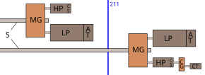
A cross compound turbine arrangement features two or more shafts not in line driving two or more generators that often operate at different speeds.
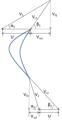
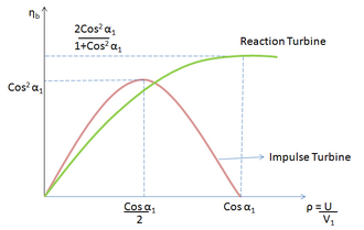
) can be defined as the ratio of the work done on the blades to kinetic energy supplied to the fluid, and is given by A stage of an impulse turbine consists of a nozzle set and a moving wheel.
The ratio of steam velocities relative to the rotor speed at the outlet to the inlet of the blade is defined by the friction coefficient
In addition, when there is no steam, a turning gear is engaged to slowly rotate the turbine to ensure even heating and prevent uneven expansion.
During normal operation in synchronization with the electricity network, power plants are governed with a five percent droop speed control.
Adjustments in power output are made by slowly raising the droop curve by increasing the spring pressure on a centrifugal governor.
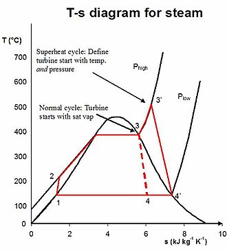
[27] The steam turbine operates on basic principles of thermodynamics using the part 3-4 of the Rankine cycle shown in the adjoining diagram.
The steam leaves the turbine as a saturated vapor (or liquid-vapor mix depending on application) at a lower temperature and pressure than it entered with and is sent to the condenser to be cooled.
The specific enthalpy is evaluated at the same steam pressure for the actual and ideal turbines in order to give a good comparison between the two.
A steam turbine is efficient only when operating in the thousands of RPM, while the most effective propeller designs are for speeds less than 300 RPM; consequently, precise (thus expensive) reduction gears are usually required, although numerous early ships through World War I, such as Turbinia, had direct drive from the steam turbines to the propeller shafts.
Reduction gears allowed turbines to operate in their efficient range at a much higher speed than the shaft, but were expensive to manufacture.
The lingering fondness for reciprocating machinery was because the US Navy had no plans for capital ships exceeding 21 knots (39 km/h; 24 mph) until after World War I, so top speed was less important than economical cruising.
The United States had acquired the Philippines and Hawaii as territories in 1898, and lacked the British Royal Navy's worldwide network of coaling stations.
[37] When US Navy warship construction resumed in the early 1950s, most surface combatants and aircraft carriers used 1,200 psi (8,300 kPa)/950 °F (510 °C) steam.
Over the next eight years the US Navy launched five additional turbo-electric-powered battleships and two aircraft carriers (initially ordered as Lexington-class battlecruisers).
Some ocean liners were also built with turbo-electric drive, as were some troop transports and mass-production destroyer escorts in World War II.
Today, propulsion steam turbine cycle efficiencies have yet to break 50%, yet diesel engines routinely exceed 50%, especially in marine applications.
As of 2024, the main propulsion steam turbines (HP & LP) for United States Navy nuclear-powered Nimitz and Ford class aircraft carriers are manufactured by the Curtiss-Wright Corporation in Summerville, SC.
The first steam turbine rail locomotive was built in 1908 for the Officine Meccaniche Miani Silvestri Grodona Comi, Milan, Italy.