Switched-mode power supply
Despite the reduced transformer size, the power supply topology and electromagnetic compatibility requirements in commercial designs result in a usually much greater component count and corresponding circuit complexity.
They are, however, more complicated; switching currents can cause electrical noise problems if not carefully suppressed, and simple designs may have a poor power factor.
A linear regulator regulates either output voltage or current by dissipating the electric power in the form of heat, and hence its maximum power efficiency is voltage-out divided by voltage-in since the voltage difference between input and output is wasted.
In contrast, a SMPS changes output voltage and current by switching ideally lossless storage elements, such as inductors and capacitors, between different electrical configurations.
Ideal switching elements (approximated by transistors operated outside of their active mode) have no resistance when "on" and carry no current when "off", and so converters with ideal components would operate with 100% efficiency (i.e., all input power is delivered to the load; no power is wasted as dissipated heat).
Other advantages include smaller size, and lighter weight from the elimination of heavy and expensive line-frequency transformers.
Very low-cost SMPSs may couple electrical switching noise back onto the mains power line, causing interference with devices connected to the same phase, such as A/V equipment.
The current drawn from the mains supply by this rectifier circuit occurs in short pulses around the AC voltage peaks.
On the other hand, if the power supply has a voltage selector switch, based on the Delon circuit, for 115/230 V (computer ATX power supplies typically are in this category), the selector switch would have to be put in the 230 V position, and the required voltage would be 325 VDC (230 × √2).
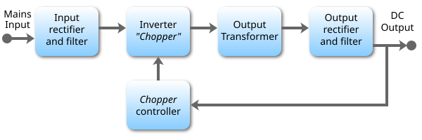
If the output is required to be isolated from the input, as is usually the case in mains power supplies, the inverted AC is used to drive the primary winding of a high-frequency transformer.
For lower voltages, Schottky diodes are commonly used as the rectifier elements; they have the advantages of faster recovery times than silicon diodes (allowing low-loss operation at higher frequencies) and a lower voltage drop when conducting.
The buck converter reduces the input voltage in direct proportion to the ratio of conductive time to the total switching period, called the duty cycle.
Switching supplies in computers, TVs and VCRs have these opto-couplers to tightly control the output voltage.
Instead, they rely on feeding a constant voltage to the input of the transformer or inductor, and assume that the output will be correct.
[38] The terminal voltage of a transformer is proportional to the product of the core area, magnetic flux, and frequency.
The laminated iron cores of lower-frequency (<400 Hz) transformers would be unacceptably lossy at switching frequencies of a few kilohertz.
Furthermore, more attention to the physical layout of the circuit board is required as parasitics become more significant, and the amount of electromagnetic interference will be more pronounced.
At 500 kHz, the skin depth in copper is about 0.003 inches (0.076 mm) – a dimension smaller than the typical wires used in a power supply.
The skin effect is exacerbated by the harmonics present in the high-speed pulse-width modulation (PWM) switching waveforms.
This creates extra load on utility lines, increases heating of building wiring, the utility transformers, and standard AC electric motors, and may cause stability problems in some applications such as in emergency generator systems or aircraft generators.
Putting a current regulated boost chopper stage after the off-line rectifier (to charge the storage capacitor) can correct the power factor, but increases the complexity and cost.
In 2001, the European Union put into effect the standard IEC 61000-3-2 to set limits on the harmonics of the AC input current up to the 40th harmonic for equipment above 75 W. The standard defines four classes of equipment depending on its type and current waveform.
AC or ≤ 42.4 V peak or ≤ 60 V DC and power limits of 250 VA apply for safety certification (UL, CSA, VDE approval).
The neutral point clamped (NPC) topology is used in power supplies and active filters and is mentioned here for completeness.
All isolated topologies include a transformer, and thus can produce an output of higher or lower voltage than the input by adjusting the turns ratio.
For power supplies without fail-safe protection, this may subject connected loads to the full input voltage and current, and wild oscillations can occur in the output.
The primary and secondary sides may be connected with a capacitor to reduce EMI and compensate for various capacitive couplings in the converter circuit, where the transformer is one.
The current flowing from line or neutral through a 2 kΩ resistor to any accessible part must, according to IEC 60950, be less than 250 μA for IT equipment.
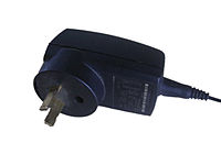
The first chargers were linear power supplies, but they quickly moved to the cost-effective ringing choke converter (RCC) SMPS topology, when new levels of efficiency were required.
Recently, the demand for even lower no-load power requirements in the application has meant that flyback topology is being used more widely; primary side sensing flyback controllers are also helping to cut the bill of materials (BOM) by removing secondary-side sensing components such as optocouplers.


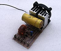
A: Bridge rectifier;
B: input filter capacitors;
Between B and C: heat sink for switching active devices of primary voltage;
C: transformer:
Between C and D: heat sink for switching active devices of at least five secondary voltages, per the ATX specification;
D: output filter coil for the secondary with the largest power rating. In close proximity, filter coils for the other secondaries;
E: output filter capacitors.
The coil and large rectangular yellow capacitor below the bridge rectifier form an EMI filter and are not part of the main circuit board.