Tantalum capacitor
It consists of a pellet of porous tantalum metal as an anode, covered by an insulating oxide layer that forms the dielectric, surrounded by liquid or solid electrolyte as a cathode.
Tantalum electrolytic capacitors are extensively used in electronic devices that require stable capacitance, low leakage current, and where reliability is crucial.
This surface area increase boosts the capacitance value by a factor of up to 200 (depending on the rated voltage) for solid tantalum electrolytic capacitors.
[7][8][9] A common figure of merit for comparing volumetric efficiency of powders is expressed in capacitance (C, usually in μF) times volts (V) per gram (g).
Figure 1 shows powders of successively finer grain, resulting in greater surface area per unit volume.
This pellet/wire combination is subsequently vacuum sintered at high temperature (typically 1200 to 1800 °C) which produces a mechanically strong pellet and drives off many impurities within the powder.
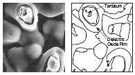
This structure is of predictable mechanical strength and density, but is also highly porous, producing a large internal surface area (see Figure 2).
The chemical equations describing the dielectric formation process at the anode are as follows:[9] The oxide forms on the surface of the tantalum, but it also grows into the material.
[12] This very high safety factor is substantiated by the failure mechanism of solid tantalum capacitors, "field crystallization".
The chemical equation is:[9] This process is repeated several times through varying specific gravities of nitrate solution, to build up a thick coat over all internal and external surfaces of the "pellet", as shown in Figure 4.
In 1952 Bell Labs researchers discovered the use of manganese dioxide as a solid electrolyte for a sintered tantalum capacitor.
[24] Although the fundamental inventions came from the Bell Labs, the innovations for manufacturing commercially viable tantalum electrolytic capacitors were done by the researchers of the Sprague Electric Company.
[25][26] His invention was supported by R. J. Millard, who introduced the "reform" step in 1955,[27][28] a significant improvement in which the dielectric of the capacitor was repaired after each dip-and-convert cycle of MnO2 deposition.
[37] This capacitor used the newly developed organic conductive polymer PEDT Poly(3,4-ethylenedioxythiophene), also known as PEDOT (trade name Baytron).
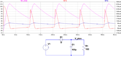
All properties can be defined and specified by a series equivalent circuit composed of an idealized capacitance and additional electrical components which model all losses and inductive parameters of a capacitor.
Nevertheless, tantalum electrolytic capacitors can withstand for short instants a reverse voltage for a limited number of cycles.
Then Z is given by In the special case of resonance, in which the both reactive resistances XC and XL have the same value (XC=XL), then the impedance will only be determined by ESR.
[49] Discussions of electrolytic capacitors historically sometimes refer to the dissipation factor, tan δ, in the relevant data sheets instead of ESR.
This dissipation power loss PL is caused by ESR and is the squared value of the effective (RMS) ripple current IR.
[43][44] Tantalum capacitors, which are exposed to surge, peak or pulse currents should be used with a voltage derating up to 70% in highly inductive circuits.
[57][58] However, in most applications where tantalum electrolytic capacitors are supporting power supply lines, dielectric absorption is not a problem.
Continuous improvement in tantalum powder and capacitor technologies have resulted in a significant reduction in the amount of impurities present, which formerly have caused most of the field crystallization failures.
[70] The extremely thin oxide film of a tantalum electrolytic capacitor, the dielectric layer, must be formed in an amorphous structure.
[72] It is believed that the voltage across the dielectric layer is the trigger mechanism for the breakdown and that the switch-on current pushes the collapse to a catastrophic failure.
Some applications like AC/AC converters with DC-link for frequency controls in three-phase grids need higher voltages than aluminum electrolytic capacitors usually offer.
[75] If the failure is a short circuit (the most common occurrence), and current is not limited to a safe value, catastrophic thermal runaway may occur.
For example a square-shaped solder point is used for positive polarity (needs to be verified on particular case measuring connection against ground, negative or positive voltage pins) Tantalum capacitors, like most other electronic components and if enough space is available, have imprinted markings to indicate manufacturer, type, electrical and thermal characteristics, and date of manufacture.
But most tantalum capacitors are chip types so the reduced space limits the imprinted signs to capacitance, tolerance, voltage and polarity.
Some non-governmental organizations are working together to raise awareness of the relationship between consumer electronic devices and conflict minerals.
An especially common application for low-voltage tantalum capacitors is power supply filtering on computer motherboards and in peripherals, due to their small size and long-term reliability.