Degree of reaction
In turbomachinery, degree of reaction or reaction ratio (denoted R) is defined as the ratio of the change in static pressure in the rotating blades of a compressor or turbine, to the static pressure change in the compressor or turbine stage.
Alternatively it is the ratio of static enthalpy change in the rotor to the static enthalpy change in the stage.
Various definitions exist in terms of enthalpies, pressures or flow geometry of the device.
In case of turbines, both impulse and reaction machines, degree of reaction is defined as the ratio of energy transfer by the change in static head to the total energy transfer in the rotor:[1]
{\displaystyle R={\frac {\text{Isentropic enthalpy change in rotor}}{\text{Isentropic enthalpy change in stage}}}}
For a gas turbine or compressor it is defined as the ratio of isentropic heat drop in the moving blades (the rotor) to the sum of the isentropic heat drops in both the fixed blades (the stator) and the moving blades:
In pumps, degree of reaction deals in static and dynamic head.
Degree of reaction is defined as the fraction of energy transfer by change in static head to the total energy transfer in the rotor:
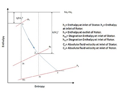
Most turbo machines are efficient to a certain degree and can be approximated to undergo isentropic process in the stage.
Where 1 to 3ss in Figure 1 represents the isentropic process beginning from stator inlet at 1 to rotor outlet at 3.
for the flow process within the stage represents the change in fluid velocity as it flows first in the stator or the fixed blades and then through the rotor or the moving blades.
Another useful definition used commonly uses stage velocities as:[2]
The degree of reaction can also be written in terms of the geometry of the turbomachine as obtained by[2]
where β3 is the vane angle of rotor outlet and β2 is the vane angle of stator outlet.
The degree of reaction now depends only on φ and
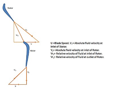
Using the velocity triangles degree of reaction can be derived as:[3]
This relation is again very useful when the rotor blade angle and rotor vane angle are defined for the given geometry.
The Figure 3[4] alongside shows the variation of total-to-static efficiency at different blade loading coefficient with the degree of reaction.
The diagram shows the optimization of total - to - static efficiency at a given stage loading factor, by a suitable choice of reaction.
It is evident from the diagram that for a fixed stage loading factor that there is a relatively small change in total-to-static efficiency for a wide range of designs.
The degree of reaction contributes to the stage efficiency and thus used as a design parameter.
Stages having 50% degree of reaction are used where the pressure drop is equally shared by the stator and the rotor for a turbine.
This reduces the tendency of boundary layer separation from the blade surface avoiding large stagnation pressure losses.
If R= 1⁄2 then from the relation of degree of reaction,|C| α2 = β3 and the velocity triangle (Figure 4.)
In addition the whirl components are also the same at the inlet of rotor and diffuser.
The same follows for a pump or compressor as shown in Figure 6.
From the relation for degree of reaction,|C| α2 < β3 which is also shown in corresponding Figure 7.
This is special case used for impulse turbine which suggest that entire pressure drop in the turbine is obtained in the stator.
It is difficult to achieve adiabatic expansion in the impulse stage, i.e. expansion only in the nozzle, due to irreversibility involved, in actual practice.
Figure 8 shows the corresponding enthalpy drop for the reaction = 0 case.