Ceramic capacitor
The expanding market of radios in the 1930s and 1940s create a demand for higher capacitance values but below electrolytic capacitors for HF decoupling applications.
Discovered in 1921, the ferroelectric ceramic material barium titanate with a permittivity in the range of 1,000, about ten times greater than titanium dioxide or mica, began to play a much larger role in electronic applications.
The fast-growing broadcasting industry after the Second World War drove deeper understanding of the crystallography, phase transitions and the chemical and mechanical optimization of the ceramic materials.
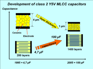
An American company in the midst of the Apollo program, launched in 1961, pioneered the stacking of multiple discs to create a monolithic block.
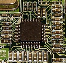
These ceramic chip capacitors were the driving force behind the conversion of electronic devices from through-hole mounting to surface-mount technology in the 1980s.
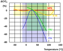
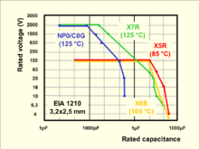
Using mixtures of paraelectric substances based on titanium dioxide results in very stable and linear behavior of the capacitance value within a specified temperature range and low losses at high frequencies.
Higher capacitance values for ceramic capacitors can be attained by using mixtures of ferroelectric materials like barium titanate together with specific oxides.
The following table shows the different definitions of the application classes for ceramic capacitors: Manufacturers, especially in the US, preferred Electronic Industries Alliance (EIA) standards.
They are suitable for bypass, coupling and decoupling applications or for frequency discriminating circuits where low losses and high stability of capacitance are less important.
With the progressive miniaturization of digital electronics in recent decades, the components on the periphery of the integrated logic circuits have been scaled down as well.
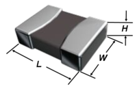
The EIA code and the metric equivalent of the common sizes of multilayer ceramic chip capacitors, and the dimensions in mm are shown in the following table.
Normally, however, the height H does not exceed the width W. Originally, MLCC electrodes were constructed out of noble metals such as silver and palladium which can withstand high sintering temperatures of 1,200 to 1,400 °C (2,190 to 2,550 °F) without readily oxidizing.
[21] These base metal electrode (BME) capacitors possessed poorer electrical characteristics; exhibiting greater shrinkage of capacitance at higher voltages and increased loss factor.
The disadvantages of BME were deemed acceptable for class 2 capacitors, which are primarily used in accuracy-insensitive, low-cost applications such as power supplies.
The following two tables, for ceramics NP0/C0G and X7R each, list for each common case size the maximum available capacitance value and rated voltage of the leading manufacturers Murata, TDK, KEMET, AVX.
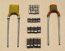
A standard multi-layer ceramic capacitor has many opposing electrode layers stacked inside connected with two outer terminations.
It is constructed like a standard two-terminal MLCC out of the stacked ceramic layers with an additional third set of shield electrodes incorporated in the chip.
[23][24][25] Capable of replacing 2 or more conventional devices, the X2Y ceramic capacitors are ideal for high frequency filtering or noise suppression of supply voltages in digital circuits, and can prove invaluable in meeting stringent EMC demands in dc motors, in automotive, audio, sensor and other applications.
[30] Ceramics are brittle, and MLCC chips surface-mount soldered to a circuit board are often vulnerable to cracking from thermal expansion or mechanical stresses like depanelization, more so than leaded through-hole components.
For example, an internal short circuit arises by the contact of two electrodes with opposite polarity, which will be produced at the break of the ceramic in the region of the terminations.
In this construction, the rigid metallic soldering connection can move against the flexible polymer layer, and thus can absorb the bending forces, without resulting in a break in the ceramic.
[38] Suppression components are connected directly to mains voltage for 10 to 20 years or more and are therefore exposed to potentially damaging overvoltages and transients.
Even when exposed to large overvoltage surges, these safety-rated capacitors must fail in a fail-safe manner that does not endanger personnel or property.
For this reason, in recent years a lot of MLCC chips for EMI/RFI suppression from different manufacturers have received approvals and fulfill all requirements given in the applicable standards.
The standardization of ceramic capacitors for lower power is oriented toward electrical and mechanical parameters as components for use in electronic equipment.
A high degree of precision and control of process parameters is necessary to keep the scattering of electrical properties for today's very thin ceramic layers within specified limits.
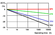
But environmental influences such as higher temperature, high humidity and mechanical stress can, over a longer period of time, lead to a small irreversible decline in capacitance, sometimes also called aging.
The voltage at the terminals generated by dielectric absorption may in some cases possibly cause problems in the function of an electronic circuit or can be a safety risk to personnel.
[57] Microphony describes the phenomenon wherein electronic components transform mechanical vibrations into an electrical signal which in many cases is undesired noise.
[58] In the reverse microphonic effect, the varying electric field between the capacitor plates exerts a physical force, moving them as a speaker.