Fiber diffraction
Such uniaxial symmetry is frequent with filaments or fibers consisting of biological or man-made macromolecules.
Materials science considers fiber symmetry a simplification, because almost the complete obtainable structure information is in a single two-dimensional (2D) diffraction pattern exposed on photographic film or on a 2D detector.
In case of fiber symmetry, many more reflections than in single-crystal diffraction show up in the 2D pattern.
The reason is that the fiber axis and the incident beam (X-rays, electrons, neutrons) cannot be perfectly oriented perpendicular to each other.
Later Rosalind Franklin and Raymond Gosling have carried out their own geometrical reasoning and presented an approximative equation for the fiber tilt angle β.
Analysis starts by mapping the distorted 2D pattern on the representative plane of the fiber.
In crystallography first an approximation of the mapping into reciprocal space is computed that is refined iteratively.
The digital method frequently called Fraser correction starts from the Franklin approximation for the tilt angle β.
It eliminates fiber tilt, unwarps the detector image, and corrects the scattering intensity.
Fibrous materials such as wool or cotton easily form aligned bundles, and were among the first biological macromolecules studied by X-ray diffraction, notably by William Astbury in the early 1930s.
On the surface of the Ewald sphere all the points of reciprocal space are found that are seen by the detector.
Two rings represent each reflection on the Polanyi sphere, because scattering is point symmetric with respect to the origin of s-space.
The position of the reflection images is a function of the orientation of the fiber in the primary beam (Polanyi equation).
Inverted, from the positions of the reflection images the orientation of the fiber can be determined, if for the Miller index
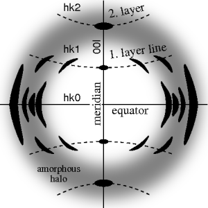
The figure on the left shows a typical fiber pattern of polypropylene before mapping it into reciprocal space.
the distance between sample and detector is computed using known crystallographic data of the reference reflection, a uniformly gridded map for the representative fiber plane in reciprocal space is constructed and the diffraction data are fed into this map.
Because of the curvature of the surface of the Ewald sphere there remain white spots at the meridian, in which structure information is missing.
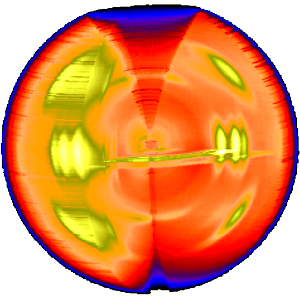
The three-dimensional sketch demonstrates that in the example experiment the collected information on the molecular structure of the polypropylene fiber is almost complete.
By rotation of the plane pattern about the meridian the scattering data collected in 4 s fill an almost spherical volume of s-space.