Flyback diode
The resistor represents the small static resistance of the inductor's wire windings.
The arc can damage the switch contacts, causing pitting and burning, eventually destroying them.
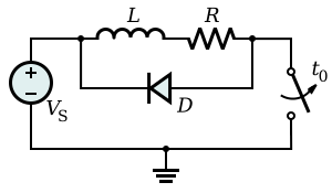
To prevent the inductive voltage pulse on turnoff, a diode is connected across the inductor, as shown in Fig.
However, when the switch is opened, the induced voltage across the inductor of opposite polarity forward biases the diode, and it conducts current, limiting the voltage across the inductor and thus preventing the arc from forming at the switch.
Each waveform was taken using a digital oscilloscope set to trigger when the voltage across the inductor dipped below zero.
In both cases, the total time for the solenoid to discharge is a few milliseconds, though the lower voltage drop across the diode will slow relay dropout.
Schottky diodes are preferred in flyback diode applications for switching power converters because they have the lowest forward drop (~0.2 V rather than >0.7 V for low currents) and are able to quickly respond to reverse bias (when the inductor is being re-energized).
Energy is dissipated in this arc primarily as intense heat, which causes undesirable premature erosion of the contacts.
Some energy is also lost from the system as a whole and from the arc as a broad spectrum of electromagnetic radiation, in the form of radio waves and light.
This approach also minimises those parts of the circuit that are subject to an unwanted high-voltage — a good engineering practice.
The voltage at an inductor is, by the law of electromagnetic induction and the definition of inductance: If there is no flyback diode but only something with great resistance (such as the air between two metal contacts), say, R2, we will approximate it as: If we open the switch and ignore VCC and R1, we get: or which is a differential equation with the solution: We observe that the current will decrease faster if the resistance is high, such as with air.
For I > 0, we can assume: so: which is: whose (first order differential equation) solution is: We can calculate the time it needs to switch off by determining for which t it is I(t) = 0.
A resistor in series with the diode will make the circulating current decay faster at the drawback of an increased reverse voltage.
Both the transistor voltages and the resistor or zener diode power ratings should be checked in this case.