Interferometry
[1] Interferometry typically uses electromagnetic waves and is an important investigative technique in the fields of astronomy, fiber optics, engineering metrology, optical metrology, oceanography, seismology, spectroscopy (and its applications to chemistry), quantum mechanics, nuclear and particle physics, plasma physics, biomolecular interactions, surface profiling, microfluidics, mechanical stress/strain measurement, velocimetry, optometry, and making holograms.
[2]: 26 The central fringe representing equal path length may be light or dark depending on the number of phase inversions experienced by the two beams as they traverse the optical system.
His interpretation in terms of the interference of waves was rejected by most scientists at the time because of the dominance of Isaac Newton's corpuscular theory of light proposed a century before.
[5] The French engineer Augustin-Jean Fresnel, unaware of Young's results, began working on a wave theory of light and interference and was introduced to François Arago.
Einstein stated that it was Fizeau's measurement of the speed of light in moving water using the Arago interferometer that inspired his theory of the relativistic addition of velocities.
[8] Interferometers and interferometric techniques may be categorized by a variety of criteria: In homodyne detection, the interference occurs between two beams at the same wavelength (or carrier frequency).
Lacking modern means of environmental temperature control, experimentalists struggled with continual fringe drift even though the interferometer might be set up in a basement.
The advantages of white light, which produced a distinctive colored fringe pattern, far outweighed the difficulties of aligning the apparatus due to its low coherence length.
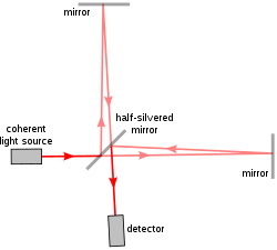
Michelson interferometers have the largest field of view for a specified wavelength, and are relatively simple in operation, since tuning is via mechanical rotation of waveplates rather than via high voltage control of piezoelectric crystals or lithium niobate optical modulators as used in a Fabry–Pérot system.
(A practical Fourier transform spectrometer would substitute corner cube reflectors for the flat mirrors of the conventional Michelson interferometer, but for simplicity, the illustration does not show this.)
[53] Neutron interferometry has been used to investigate the Aharonov–Bohm effect, to examine the effects of gravity acting on an elementary particle, and to demonstrate a strange behavior of fermions that is at the basis of the Pauli exclusion principle: Unlike macroscopic objects, when fermions are rotated by 360° about any axis, they do not return to their original state, but develop a minus sign in their wave function.
In telecommunications, wavelength-division multiplexing, the technology that enables the use of multiple wavelengths of light through a single optical fiber, depends on filtering devices that are thin-film etalons.
Michelson (1918) criticized the Twyman–Green configuration as being unsuitable for the testing of large optical components, since the light sources available at the time had limited coherence length.
[60] Mach–Zehnder interferometers are being used in integrated optical circuits, in which light interferes between two branches of a waveguide that are externally modulated to vary their relative phase.
In recent years, computer-generated holograms (CGHs) have begun to supplement null correctors in test setups for complex aspheric surfaces.
[65] In telecommunication networks, heterodyning is used to move frequencies of individual signals to different channels which may share a single physical transmission line.
Continuous wave (CW) doppler radar detectors are basically heterodyne detection devices that compare transmitted and reflected beams.
It has application in optical fiber communications, in various high resolution spectroscopic techniques, and the self-heterodyne method can be used to measure the linewidth of a laser.
[68][69] One of the most common industrial applications of optical interferometry is as a versatile measurement tool for the high precision examination of surface topography.
[79] Phase shifting interferometry overcomes these limitations by not relying on finding fringe centers, but rather by collecting intensity data from every point of the CCD image sensor.
17, multiple interferograms (at least three) are analyzed with the reference optical surface shifted by a precise fraction of a wavelength between each exposure using a piezoelectric transducer (PZT).
Early lasers were relatively weak and photographic plates were insensitive, necessitating long exposures during which vibrations or minute shifts might occur in the optical system.
[92] Eventually, several independent groups of experimenters in the mid-60s realized that the fringes encoded important information about dimensional changes occurring in the subject, and began intentionally producing holographic double exposures.
Data acquired using the space shuttle Endeavour's X-band Synthetic Aperture Radar on April 13, 1994 and October 4, 1994 were used to generate interferometric fringes, which were overlaid on the X-SAR image of Kilauea.
[98][99] A method of establishing precise geodetic baselines, invented by Yrjö Väisälä, exploited the low coherence length of white light.
Initially, white light was split in two, with the reference beam "folded", bouncing back-and-forth six times between a mirror pair spaced precisely 1 m apart.
[75] Optical interferometry, applied to biology and medicine, provides sensitive metrology capabilities for the measurement of biomolecules, subcellular components, cells and tissues.
[101] Many forms of label-free biosensors rely on interferometry because the direct interaction of electromagnetic fields with local molecular polarizability eliminates the need for fluorescent tags or nanoparticle markers.
Optical coherence tomography (OCT) is a medical imaging technique using low-coherence interferometry to provide tomographic visualization of internal tissue microstructures.
[112] These methods provide higher contrast compared to normal absorption-contrast x-ray imaging, making it possible to see smaller details.