Lattice network
A symmetrical lattice is a two-port electrical wave filter in which diagonally-crossed shunt elements are present – a configuration which sets it apart from ladder networks.
The filter properties of this circuit were first developed using image impedance concepts, but later the more general techniques of network analysis were applied to it.
A commonly used short-hand version is shown on the right, with dotted lines indicating the presence the second pair of matching impedances.
It is possible with this circuit to have the characteristic impedance specified independently of its transmission properties,[5] a feature not available to ladder filter structures.
[6] It is possible to redraw the lattice in the Wheatstone bridge configuration[7] (as shown in the article Zobel network).
(In practice, the choices for γ and zo are restricted to those which result in physically realisable impedances for Za and Zb .)
The transition region of the filter, where a change from one set of conditions to another occurs, can be made as narrow as required by increasing the complexity of Za and Zb .
The phase response of the filter in the pass-band is governed by the locations (spacings) of the resonant and anti-resonant frequencies of Za and Zb .
The parameter yo is termed the index function and zo is the normalised characteristic impedance of the network.
In the case of a low-pass filter, for example, where the mismatch is most severe near the cut-off frequency, the transition from pass-band to stop-band is far less sharp than expected.
To minimise the mismatch problem, various forms of image filter end terminations were proposed by Zobel and others, but the inevitable compromises led to the method falling out of favour.
When resistors are present within Za and Zb then, provided the duality condition still applies, a circuit will be constant-resistance but have a variable amplitude response.
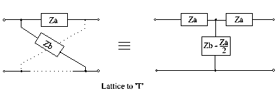
The simple conversion procedure shown in the previous section can only be applied in a limited set of conditions – generally, some form of bridged-T circuit is necessary.
When Cb > Ca, an alternative procedure is necessary, where common inductors are first extracted from the lattice arms.
In the case of all-pass networks, there is no attenuation region, so the impedances Za and Zb (of the lattice) are duals of each other at all frequencies and Z0 is always resistive, equal to R0.
Where a synthesis procedure results in several possible lattice solutions, the one that is easiest to convert is usually chosen.
Often, the conversion process results in mutually coupled inductors, as shown earlier, but it is sometimes possible to avoid these altogether, if a high value of insertion loss can be tolerated,[24] or if a combination of circuits in parallel is considered.
Sometimes synthesis of a lattice can be achieved by simply apportioning parts of an expression in z12, or in z11 and z12, directly to the impedances Za and Zb, as in the following example.
The first step is to express the input impedance ZI of a terminated network in terms of its z-parameters.
So, although it is possible to synthesize a single lattice with complicated impedances Za and Zb, it is practically easier to construct and align a cascade of simpler circuits.
All-pass networks have a constant gain with frequency, but they have a phase response which varies in some chosen manner.
Similarly Zb is an inductor 1/a in series with a capacitor of value a/b and the network is shown at the right hand side below.
For example, the article Lattice delay network gives pole-zero locations for many all-pass transfer functions which approximate to a linear phase characteristic.
So Z1 can be realized as an R-C ladder network, in the Cauer manner,[21] and is shown as part of the bridged-T circuit below.
[37] George Ashley Campbell was a key contributor to this new filter theory, as was Otto Julius Zobel.
[39] Zobel's article on filter theory and design,[35] published at about this time, mentioned lattices only briefly, with his main emphasis on ladder networks.
It was only later, when Zobel considered the simulation and equalisation of telephone transmission lines, that he gave the lattice configuration more attention.
[40] (The telephone transmission lines of the time had a balanced-pair configuration with a nominal characteristic impedance of 600 ohms,[41] so the lattice equaliser, with its balanced structure, was particularly appropriate for use with them).
Later workers, especially Hendrik Wade Bode,[20][36] gave greater prominence to lattice networks in their filter designs.
During the 1930s, as techniques in network analysis and synthesis became better developed, designing ladder filters by image methods became less popular.