Net force
When the net force is applied at a specific point on an object, the associated torque can be calculated.
This is not always true, especially in complex topics like the motion of spinning objects or situations where everything is perfectly balanced, known as static equilibrium.
When we need to visually represent a force, we draw a line segment.
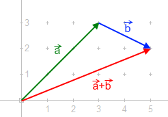
One of the essential concepts in physics is that forces can be added together, which is the basis of vector addition.
This concept has been central to physics since the times of Galileo and Newton, forming the cornerstone of Vector calculus, which came into its own in the late 1800s and early 1900s.
[3] The picture to the right shows how to add two forces using the "tip-to-tail" method.
Grasping this concept is fundamental to understanding how forces interact and combine to influence the motion and equilibrium of objects.
It's important to remember that to add these forces together, they need to be considered at the same point.
However, the net force alone may not necessarily preserve the motion of the body.
This resultant force-and-torque combination will have the same effect on the body as all the original forces and their associated torques.
A force is known as a bound vector—which means it has a direction and magnitude and a point of application.
The doubling of this length is easily achieved by defining a segments BC and DC parallel to AD and AB, respectively, to complete the parallelogram ABCD.
The diagonal AC of this parallelogram is the sum of the two force vectors.
The problem is usually resolved in the following ways: In any case, the analysis of the rigid body motion begins with the point force model.
And when a force acting on a body is shown graphically, the oriented line segment representing the force is usually drawn so as to "begin" (or "end") at the application point.
acts at the application point H on a free rigid body.
As the illustration suggests, the torque does not change (the same lever arm) if the application point is moved along the line of the application of the force (dotted black line).
More formally, this follows from the properties of the vector product, and shows that rotational effect of the force depends only on the position of its line of application, and not on the particular choice of the point of application along that line.
The right-hand rule relates this direction to the clockwise or counterclockwise rotation in the plane of the drawing.
is calculated with respect to the axis through the center of mass that is parallel with the torque.
If the body shown in the illustration is a homogeneous disc, this moment of inertia is
An interesting special case is a torque-free resultant, which can be found as follows: where
The diagram opposite illustrates simple graphical methods for finding the line of application of the resultant force of simple planar systems: In general, a system of forces acting on a rigid body can always be replaced by one force plus one pure (see previous section) torque.
The line of action can be selected arbitrarily, but the additional pure torque depends on this choice.
In a special case, it is possible to find such line of action that this additional torque is zero.
This is useful, both conceptually and practically, because the body moves without rotating as if it was a particle.