Phase margin
In electronic amplifiers, the phase margin (PM) is the difference between the phase lag φ (< 0) and -180°, for an amplifier's output signal (relative to its input) at zero dB gain - i.e. unity gain, or that the output signal has the same amplitude as the input.
Typically the open-loop phase lag (relative to input, φ < 0) varies with frequency, progressively increasing to exceed 180°, at which frequency the output signal becomes inverted, or antiphase in relation to the input.
Thus positive PM is a "safety margin" that ensures proper (non-oscillatory) operation of the circuit.
Phase margin indicates relative stability, the tendency to oscillate during its damped response to an input change such as a step function.
Gain margin indicates absolute stability and the degree to which the system will oscillate, without limit, given any disturbance.
It is the additional phase shift that can be tolerated, with no gain change, while remaining stable[3] .Gain margin is the difference (expressed as a positive dB value) between 0 dB and the magnitude of the loop transfer function at the frequency where the phase shift is 180°.
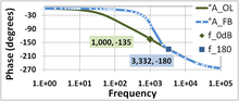
This means that at the frequency at which the open and closed loop gains meet, the phase angle is −135°.
See Warwick[5] or Stout[6] for a detailed analysis of the techniques and results of compensation to ensure adequate phase margins.
A phase margin of 60 degrees is also a magic number because it allows for the fastest settling time when attempting to follow a voltage step input (a Butterworth design).