Plugboard
A plugboard or control panel (the term used depends on the application area) is an array of jacks or sockets (often called hubs) into which patch cords can be inserted to complete an electrical circuit.
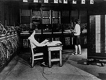
Control panels are sometimes used to direct the operation of unit record equipment, cipher machines, and early computers.
The wiring on a plugboard connects these devices to perform a specific function, say reading cards and summing up the numbers punched in a group of columns.
Inspired by telephone switchboards, Otto Schäffler invented the plugboard in order to easily reprogram tabulators.
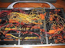
Unit record equipment was typically configured for a specific task using a removable control panel.
Perhaps the closest modern analog is the field-programmable gate array, where a fixed number of logic components are made available and their interconnection wiring is determined by the user.
Wiring a unit record control panel required knowledge of the machine's components and their timing constraints.
The action caused by an impulse on a wire depended on when in the cycle it occurred, a simple form of time-division multiplexing.
The control panel for each machine type presented exit (output) and entry (input) hubs in logical arrangements.
In practice the plugboard did improve the security of the cypher being generated, but as it did not change with every keypress, unlike the rotors, its impact was limited.
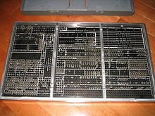
Plugboards remained in use in specialty-purpose computers for some time, acting as a read only memory (ROM) but able to be manually reprogrammed in the field.
One example is the Ferranti Argus computer, used on the Bristol Bloodhound missile, which feature a plugboard programmed by inserting small ferrite rods into slots, in effect creating a read-only core memory by hand.