Rivet
The rivets themselves were essentially short rods of metal, which metalworkers hammered into a pre-drilled hole on one side and deformed on the other to hold them in place.
Solid rivets are driven using a hydraulically, pneumatically, or electromagnetically actuated squeezing tool or even a handheld hammer.
Solid rivets are also used by some artisans in the construction of modern reproduction of medieval armour, jewellery and metal couture.
Indeed, the latest steel construction specifications published by AISC (the 14th Edition) no longer cover their installation.
The reason for the change is primarily due to the expense of skilled workers required to install high-strength structural steel rivets.
In the seismic retrofit of such structures, it is common practice to remove critical rivets with an oxygen torch, precision ream the hole, then insert a machined and heat-treated bolt.
The purpose of this hole is to reduce the amount of force needed for application by rolling the tubular portion outward.
The type of equipment used to apply semi-tubular rivets ranges from prototyping tools to fully automated systems.
Blind rivets, commonly referred to as "pop" rivets (POP is the brand name of the original manufacturer, now owned by Stanley Engineered Fastening, a division of Stanley Black & Decker) are tubular and are supplied with a nail-like mandrel through the center which has a "necked" or weakened area near the head.
The compression force between the head of the mandrel and the tool expands the diameter of the tube throughout its length, locking the sheets being fastened if the hole was the correct size.
In 1916, Royal Navy reservist and engineer Hamilton Neil Wylie filed a patent for an "improved means of closing tubular rivets" (granted May 1917).
By 1928, the George Tucker Eyelet Company, of Birmingham, England,[6] produced a "cup" rivet based on the design.
It required a separate GKN mandrel and the rivet body to be hand-assembled prior to use for the building of the Siskin III aircraft.
The United Shoe Machinery Co. produced the design in the U.S. as inventors such as Carl Cherry and Lou Huck experimented with other techniques for expanding solid rivets.
However, in recent years automated riveting systems have become popular in an effort to reduce assembly costs and repetitive disorders.
A method popularized by Chris Heintz of Zenith Aircraft uses a common flat-head (countersunk) rivet which is drawn into a specially machined nosepiece that forms it into a round-head rivet, taking up much of the variation inherent in hole size found in amateur aircraft construction.
These splits cause the shaft to fold and flare out (similar to the wings on a toggle bolt's nut) as the mandrel is drawn into the rivet.
After installation, the head and mandrel are shaved off flush resulting in an appearance closely resembling a brazier head-driven rivet.
[10] A flush rivet is used primarily on external metal surfaces where good appearance and the elimination of unnecessary aerodynamic drag are important.
Countersunk or flush rivets are used extensively on the exterior of aircraft for aerodynamic reasons such as reduced drag and turbulence.
Originally, Cherry friction locks were available in two styles, hollow shank pull-through and self-plugging types.
The pull-through type is no longer common; however, the self-plugging Cherry friction-lock rivet is still used for repairing light aircraft.
With the influence of the upsetting die, the tail end of the rivet flares and interlocks into the bottom sheet forming a low profile button.
Depending on the rivet setter configuration, i.e. hydraulic, servo, stroke, nose-to-die gap, feed system etc., cycle times can be as quick as one second.
[16][17] Benefits include low energy demands, no heat, fumes, sparks or waste and very repeatable quality.
To become a proper fastener, a rivet should be placed in a hole ideally 4–6 thousandths of an inch larger in diameter.
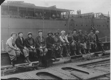
[19] A large number of countries used rivets in the construction of armored tanks during World War II, including the M3 Lee (General Grant) manufactured in the United States.
[20] In this process, the installer places a rivet gun against the factory head and holds a bucking bar against the tail or a hard working surface.
The inspector taps the head (usually the factory head) of the rivet with the hammer while touching the rivet and base plate lightly with the other hand and judges the quality of the audibly returned sound and the feel of the sound traveling through the metal to the operator's fingers.
Occasionally rivets also undergo performance testing for other critical features, such as pushout force, break load and salt spray resistance.