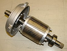
Squirrel-cage rotor
By adjusting the shape of the bars in the rotor, the speed-torque characteristics of the motor can be changed, to minimize starting current or to maximize low-speed torque, for example.
Squirrel-cage induction motors are very prevalent in industry, in sizes from below 1 kilowatt (1.3 hp) up to tens of megawatts (tens-of-thousand horsepower).
Galileo Ferraris described an induction machine with a two-phase stator winding and a solid copper cylindrical armature in 1885.
By the end of the 19th century induction motors were widely applied on the growing alternating-current electrical distributions systems.
Internally it contains longitudinal conductive bars (usually made of aluminium or copper) set into grooves and connected at both ends by shorting rings forming a cage-like shape.
A very common structure for smaller motors uses die cast aluminium poured into the rotor after the laminations are stacked.
Since the voltage developed in the squirrel cage winding is very low, and the current very high, no intentional insulation layer is present between the bars and the rotor steel.
The greatest common divisor of 36 and 40 is 4, with the result that no more than 4 bars of the stator and rotor can be aligned at any one time, which also reduces torque fluctuations.
It is made of thin laminations, separated by varnish insulation, to reduce eddy currents circulating in the core.
Generally, thick bars have good torque and are efficient at low slip, since they present lower resistance to the EMF.
As the motor accelerates, the slip frequency decreases and induced current flows at greater depths in the winding.
For this to work the motor must see a reactive load, and either be connected to a grid supply or an arrangement of capacitors to provide excitation current.