Gimbal lock
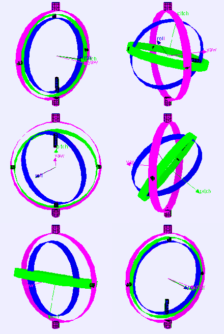
Gimbal lock is the loss of one degree of freedom in a multi-dimensional mechanism at certain alignments of the axes.
In a three-dimensional three-gimbal mechanism, gimbal lock occurs when the axes of two of the gimbals are driven into a parallel configuration, "locking" the system into rotation in a degenerate two-dimensional space.
Gimbals are typically nested one within another to accommodate rotation about multiple axes.
In compasses and flywheel energy storage mechanisms they allow objects to remain upright.
Although the ratio is infinite only at the point of gimbal lock, the practical speed and acceleration limits of the gimbals—due to inertia (resulting from the mass of each gimbal ring), bearing friction, the flow resistance of air or other fluid surrounding the gimbals (if they are not in a vacuum), and other physical and engineering factors—limit the motion of the platform close to that point.
The theodolite is a telescope mounted on a tripod so that it can move in azimuth and elevation to track the helicopter.
The helicopter flies towards the theodolite and is tracked by the telescope in elevation and azimuth.
The telescope cannot track this maneuver without a discontinuous jump in one or both of the gimbal orientations.
So there is an infinity of directions around zenith for which the telescope cannot continuously track all movements of a target.
To recover from gimbal lock the user has to go around the zenith – explicitly: reduce the elevation, change the azimuth to match the azimuth of the target, then change the elevation to match the target.
Consider a case of a level-sensing platform on an aircraft flying due north with its three gimbal axes mutually perpendicular (i.e., roll, pitch and yaw angles each zero).
If the aircraft pitches up 90 degrees, the aircraft and platform's yaw axis gimbal becomes parallel to the roll axis gimbal, and changes about yaw can no longer be compensated for.
In the context of inertial navigation systems, that can be done by mounting the inertial sensors directly to the body of the vehicle (this is called a strapdown system)[3] and integrating sensed rotation and acceleration digitally using quaternion methods to derive vehicle orientation and velocity.
[4] A well-known gimbal lock incident happened in the Apollo 11 Moon mission.
[5] Some of the reasoning behind this decision is apparent from the following quote: The advantages of the redundant gimbal seem to be outweighed by the equipment simplicity, size advantages, and corresponding implied reliability of the direct three degree of freedom unit.They preferred an alternate solution using an indicator that would be triggered when near to 85 degrees pitch.
Near that point, in a closed stabilization loop, the torque motors could theoretically be commanded to flip the gimbal 180 degrees instantaneously.
Instead, in the LM, the computer flashed a "gimbal lock" warning at 70 degrees and froze the IMU at 85 degreesRather than try to drive the gimbals faster than they could go, the system simply gave up and froze the platform.
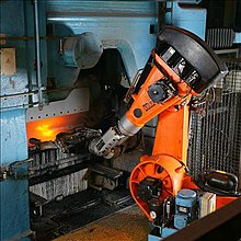
The second wrist axis then attempts to spin 180° in zero time to maintain the orientation of the end effector.
The result of a singularity can be quite dramatic and can have adverse effects on the robot arm, the end effector, and the process.
[7] The problem of gimbal lock appears when one uses Euler angles in applied mathematics; developers of 3D computer programs, such as 3D modeling, embedded navigation systems, and video games must take care to avoid it.
In formal language, gimbal lock occurs because the map from Euler angles to rotations (topologically, from the 3-torus T3 to the real projective space RP3, which is the same as the space of rotations for three-dimensional rigid bodies, formally named SO(3)) is not a local homeomorphism at every point, and thus at some points the rank (degrees of freedom) must drop below 3, at which point gimbal lock occurs.
, the above expression becomes equal to: Carrying out matrix multiplication: And finally using the trigonometry formulas: Changing the values of
It is possible to imagine an airplane rotated by the above-mentioned Euler angles using the X-Y-Z convention.
Because of gimbal lock, it has lost one of the degrees of freedom - in this case the ability to roll.
It is also possible to choose another convention for representing a rotation with a matrix using Euler angles than the X-Y-Z convention above, and also choose other variation intervals for the angles, but in the end there is always at least one value for which a degree of freedom is lost.
The cause of gimbal lock is the representation of orientation in calculations as three axial rotations based on Euler angles.
The resulting orientation must be re-normalized to prevent the accumulation of floating-point error in successive transformations.
For matrices, re-normalizing the result requires converting the matrix into its nearest orthonormal representation.


